1. Definition: Interference zone is commonly understood as the robot TCP (tool center) point entering a configurable area.
To inform peripheral equipment or field personnel of this state — force output a signal (to inform peripheral equipment);
Stop the alarm (inform the scene personnel). Because the general input and output signals can be considered interference, interference
Block output is mandatory, so it is necessary to use interference block output when it comes to security. Generally applied in
Injection molding machine, die casting machine feeding and unloading and multiple robots have a common working area.
2. Setting method:
Yaskawa robot can be set in the following three ways:
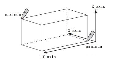
Enter the maximum/minimum value for the cube coordinates.
② Move the robot to the position of the maximum/minimum of the cube coordinates by axis operation.
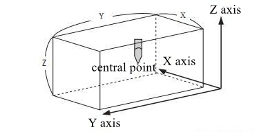
③ After the length of three sides of the cube is input, the robot is moved to the center point by axis operation.
3. Basic operations
1. Select Robot from the main menu.
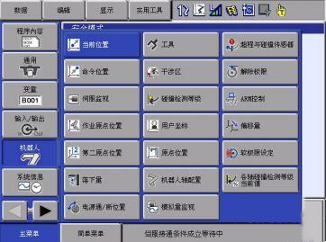
2. Select the interference zone
- The interference area screen is displayed.
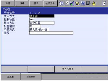
3. Set the target interference signal
- Press [Turn page] or enter a value to switch to the target interference signal.
- When entering the value, select “Enter the specified page”, enter the target signal number and press “Enter”.
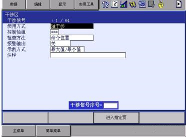
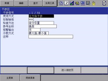
4. Select Method of Use
- Each time you press [Select], “Axis Interference” and “cube interference” will alternate. Set “Cube interference”.
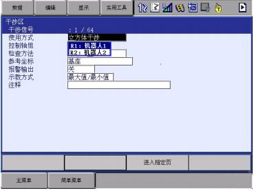
5. Select Control Axis Group.
- The selection dialog box is displayed.
Select the target control axis group.
5. Select Control Axis Group.
- The selection dialog box is displayed.
Select the target control axis group.
7. Select “Check Method”
- Each time you press [Select], Command Position and Feedback Position switch alternately.
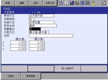
8. Select Alarm Output
- Each time you press [Select], the values of None and Yes switch alternately.
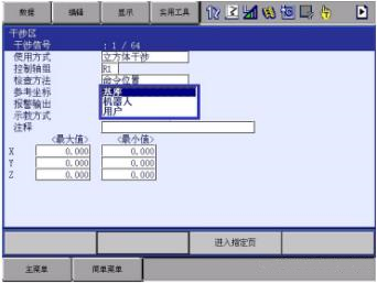
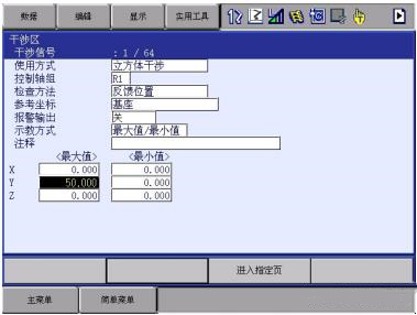
9. Enter “Max/min” for cube coordinates
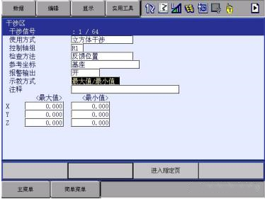
1. Select “Teaching method”
(1) Each time you press [Select], “Max/Min” and “Center Position” will be switched alternately.
(2) Set the maximum value/minimum value.
2. Enter the “maximum” and “minimum” values and press Enter.
– The cube interference zone is set.
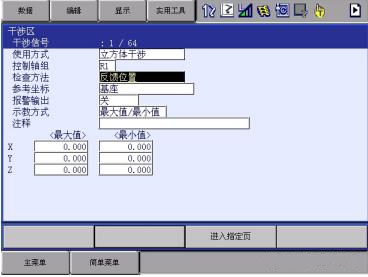
4. Parameter Description
Usage: Select the cube/axis interference zone
Control SHAFT group: Select the ROBOT group/EXTERNAL shaft group to be set
Check METHOD: SET if there is interference signal, the robot can immediately stop the action, (the interference between robots using cube interference signal). Set the check method to Command Location. If the “feedback position” is set, the robot will slow down and stop after entering the interference zone.
If THE INTERFERENCE SIGNAL IS USED TO OUTPUT THE ROBOT POSITION TO the outside world, it is set to “FEED-BACK” to output the signal in a more timely manner.
Alarm output: if it is closed, only the output signal is not alarm in the entering area. If it is opened, the alarm stops in the entering area
Teaching method: Maximum/minimum value or center location can be selected
5. Signal description
YRC1000 control cabinet factory configuration can be found on the CN308 plug two cube output, two forbidden to enter the interference area, according to the number can be corresponding to the interference area file number.
When the point position is not suitable for use or the control cabinet is YRC1000micro, the input and output of other interference areas can be mapped out by modifying the “user ladder diagram”.
Post time: Nov-09-2022